
Wiring diagrams are key to understanding and building electrical systems. They give you a clear and concise way to see the wires, connections and components so you can diagnose, repair and install accurately.
What is a Wiring Diagram in Automotive?
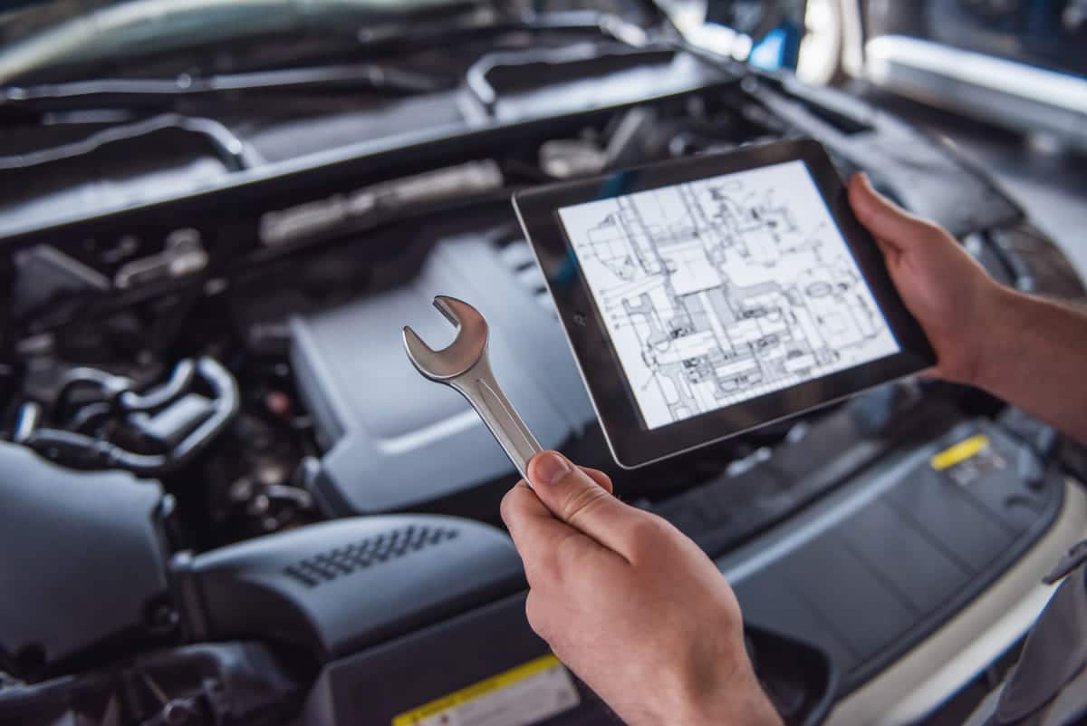
An automotive wiring diagram is a detailed visual representation of the electrical system or circuitry in a vehicle. It shows components and connections so you can see how the electricity flows through the vehicle’s systems.
These diagrams are used for multiple purposes in the automotive industry. They help diagnose electrical problems, guide repairs and ensure proper installation. Technicians use wiring diagrams to follow circuits, find faults and verify connections.
Technicians and engineers use these diagrams every day. They refer to them to find components, understand circuit functions and do accurate repairs. Wiring diagrams also help design new electrical systems and integrate aftermarket modifications.
Wiring diagrams make complex electrical systems simple. They provide the information you need for troubleshooting and maintenance. With these visual tools professionals can work smarter.
What is an Automotive Electrical System?
An automotive electrical system has components that generate, store and use electricity in a vehicle. This system powers functions like starting the engine, lighting and operating electronic devices.
Components of an Automotive Electrical System
- Magneto: A magneto provides current to the in spark-ignition engines like petrol engines. It has three components: permanent magnets, a coil and a cranking mechanism. This converts mechanical energy into electrical energy and produces a steady output regardless of load variations.
- Generator/Dynamo: A generator provides electrical energy to charge the battery and gets its drive from the engine through a fan belt. It converts mechanical energy into DC. The main components are the frame, armature and field coils. Dynamos use rotating coils and a magnetic field to convert mechanical rotation into an electrical supply.
- : An alternator is an AC generator and part of a vehicle’s charging system. It produces AC power which is quickly converted to DC for the vehicle’s 12-volt system. The main components are the frame or housing, rotor with electromagnets, stator and slip rings and brushes.
- Cut-out Relay: Also known as a circuit breaker, a cut-out relay regulates and cuts the current to the battery. It prevents the battery from discharging into the generator when the engine is running low. It also maintains a voltage of 13.5 to 14.5 volts to protect other electrical components.
- Battery: The battery stores electrical energy in DC form for future use. The positive terminal connects directly to the engine motor to start the engine. The alternator (automotive) charges the battery when the engine is running. When the engine is off the battery powers the vehicle’s electrical components
Components work together in this system to function smoothly. The battery provides power to the starter motor to start the engine. Once the engine is running the alternator charges the battery. Wiring ensures all components talk to each other.
This system also powers other functions like lights, infotainment systems and features. Proper maintenance of the automotive electrical system ensures vehicle performance and driver safety
References
- Automotive Electrical Systems. Technosoft Engineering. Retrieved from
- . Wikipedia. Retrieved from
What is the Principle of a Wiring Diagram?
A wiring diagram visually shows electrical circuits and systems. It makes complex electrical layouts simple so you can see how components connect and work together.
Symbols and notations make electrical parts look the same. Common symbols for switches, resistors and other components make diagrams universal and easy to read.
Wiring diagrams show information by showing lines and connections. Lines are wires and connections are where wires meet components. This makes troubleshooting and installation accurate.
Diagrams also use labels and color codes for clarity. Labels are for components and their functions. Color codes are for different types of wires to identify quickly and reduce errors.
By following these rules wiring diagrams are a guide for building, maintaining and repairing electrical systems. They are essential tools for engineers, technicians and electricians.
References
- How to Read an Automotive Wiring Diagram. Solera. Retrieved from
- Document from U.S. Department of Defense. Retrieved from
What Type of Wire is Used in Automotive?
Automotive primary wire is a type of electrical wire used in vehicles. Made from copper or aluminium it connects various electrical components. Primary wire is thicker than regular electrical wire and insulated with durable materials like PVC. It can withstand high temperatures and vibrations found in vehicles. Applications are engine wiring, headlights, taillights and interior .
Here are Different Types of Wire by Insulation:
Choose the right automotive wire for the environment. PVC and Cross-Link wires have different temperature ratings for different areas in the vehicle system.
PVC Automotive Primary Wire:
PVC insulation is durable for under-hood or cabin applications. It resists oil, grease and acids perfect for automotive use.
- GPT Wire: Standard wall wire for trailer and general circuit wiring. Operating temperature -40°C to 85°C suitable for most automotive applications.
- TWP Wire: Thin-walled wire up to 105°C. Lightweight and durable for many applications.
- HDT Wire: Heavy-duty wire with thick insulation to withstand physical wear. Up to 85°C.
Cross-Linked Primary Wire
Cross-linked wires have better heat and flexibility for demanding applications.
- GXL Wire: Thin-walled, lightweight wire with a heat rating of up to 125°C. Used in trucks and trailers.
- SXL Wire: General circuit wiring. Good heat and abrasion resistance. Operating temperature -40°C to 125°C.
- TXL Wire: Thin-walled wire with high heat and flexibility. For tight spaces and low temperature applications -40°C to 125°C.
Different wire types affect electrical performance and safety. Using the right wire ensures reliable connections, and minimizes electrical failures and overall vehicle safety.
References
- Automotive Primary Wire. IEWC. Retrieved from
- Differences Between the Types of Primary Automotive Wires. Lapp Tannehill. Retrieved from
How Does Automotive Wiring Work?
Automotive wiring is the systematic connection of electrical components in a vehicle. It makes sure power and signals travel efficiently between parts to function properly.
Automotive wiring uses circuits to connect electrical components. Each circuit has a power source, conductors (wires) and load (component). The is the power source, wires transmit electricity to components like lights or sensors.
Wiring harnesses bundle multiple wires together to make installation easier and reduce clutter. Engineers design harnesses based on the vehicle layout and electrical requirements. They use software to create detailed schematics to ensure accuracy.
- Step 1: Planning: Engineers study the vehicle’s electrical needs and plan the wiring routes.
- Step 2: Design: Using CAD software they create detailed diagrams of wire paths and connections.
- Step 3: Prototyping: They build a prototype harness and test it for fit and function.
- Step 4: Production: Manufacturers produce harnesses in bulk based on the approved design.
Ensuring Reliability and Safety
Manufacturers take several measures to ensure reliable and safe automotive wiring. They use high quality materials and follow strict standards. Insulation protects wires from heat, moisture and wear. Connectors ensure secure and corrosion resistant connections.
- Testing: Mechanical, thermal and electrical testing.
- Quality Control: Continuous monitoring during production to ensure consistency and to specifications.
- Compliance: Compliance to industry standards like ISO and SAE for global reliability and safety.
By following these guidelines automotive wiring systems are efficient and reliable and support the overall vehicle performance and safety.
Reference
- How Car Electrical Systems Work. How a Car Works. Retrieved from
How Do You Test Automotive Wiring?
Testing automotive wiring ensures electrical systems work properly. It helps to find and fix issues and maintain vehicle safety and performance.
Tools and Methods
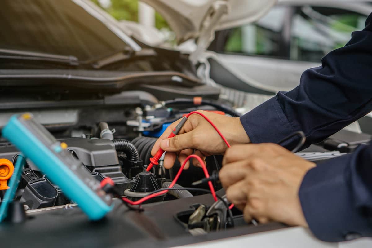
Common tools for testing automotive wiring are multimeters, test lights and circuit testers. These tools measure voltage, continuity and resistance.
- Multimeter: Measures voltage, current and resistance. Use it to check power supply and circuit integrity.
- Test Light: Shows presence of voltage in a circuit. Good for quick checks.
- Circuit Tester: Checks for continuity and proper connections. Helps to find broken wires or faulty connections.
Troubleshooting and Diagnosing Electrical Problems
To troubleshoot and diagnose electrical problems follow a step by step approach:
- Visual Inspection: Look for obvious signs of damage like frayed wires or loose connections.
- Test for Continuity: Use a multimeter to check for no breaks in the wire.
- Check Voltage: Verify the correct voltage reaches each component.
- Inspect Grounds: Ensure all ground connections are secure and free from corrosion.
Common Problems and Solutions
Common problems in automotive wiring are short circuits, open circuits and corrosion.
- Short Circuits: When wires touch and create an unintended path. Use insulation tape or replace damaged wires.
- Open Circuits: When a wire breaks or disconnects. Find and reconnect or replace broken wires.
- Corrosion: Affects connections and causes resistance. Clean corroded terminals and apply dielectric grease to prevent future corrosion.
By following these tools and methods you can test and maintain automotive wiring and ensure the vehicle’s electrical systems are reliable and safe.
References
- How to Test Your Car’s Electrical System. Auto Tech West Islip. Retrieved from
- Wiring Diagram. Wikipedia. Retrieved from
- Cooling System. Encyclopaedia Britannica. Retrieved from
- Automotive Primary Wire. IEWC. Retrieved from https://www.iewc.com/resources/technical-guide/automotive-primary-wire